banner
Статья Клапанов
Дома

Статья Клапанов

Правила технического обслуживания задвижек

Правила технического обслуживания задвижек

  • 2024/07/11

1. Introduction to Gate Valves

1.1 Working principle and function of gate valve

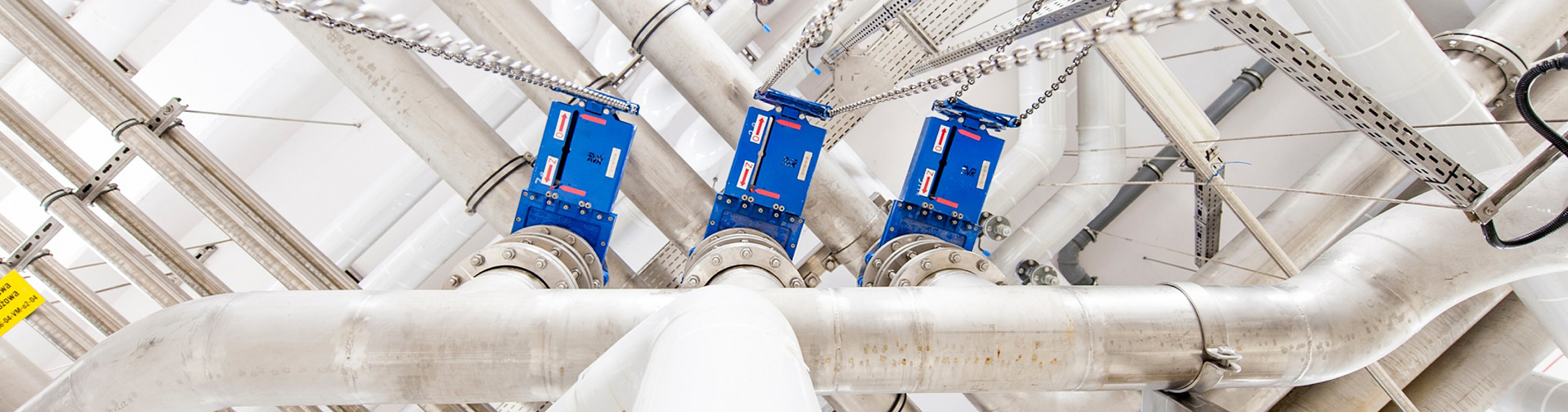
Gate valves belong to the block valve category and are usually installed on pipelines with a diameter greater than 100mm to cut off or connect the flow of medium inside the pipeline. Due to the disc shape of the valve, it is commonly referred to as a gate valve. Gate valves have advantages such as effortless opening and closing, and low flow resistance. But the sealing surface is prone to wear and leakage, with a large opening stroke and difficult maintenance. Gate valves cannot be used as regulating valves and must be in the fully open or fully closed position. The working principle is that when the gate valve is closed, the valve stem moves downwards, relying on the smooth and consistent height of the gate valve sealing surface and the valve seat sealing surface to prevent the flow of medium, and relying on the top wedge to increase the sealing effect. Its closure moves vertically along the centerline. There are many types of gate valves, which can be divided into wedge type and parallel type according to their types. Each type can be divided into single gate and double gate.

1.2 Construction
The gate valve body adopts a self sealing form. The connection method between the valve cover and valve body is to use the upward pressure of the medium inside the valve to compress the sealing packing and achieve the purpose of sealing. The sealing packing of the gate valve is sealed with high-pressure asbestos packing with copper wire.
The structure of gate valve mainly consists of valve body, valve cover, frame, valve stem, left and right valve discs, packing sealing device, etc.
The valve body material is divided into two types: carbon steel and alloy steel, depending on the pressure and temperature of the pipeline medium. Valves typically installed in superheated steam systems, with temperatures above 450 ℃, and valve bodies made of alloy materials, such as boiler exhaust valves. For valves installed in water supply systems or pipelines with a medium temperature t ≤ 450 ℃, carbon steel valve body material is sufficient.

Gate valves are generally installed and used on steam and water pipelines with a diameter of DN ≥ 100mm. There are three types of nominal diameters for gate valves in the WGZ1045/17.5-1 boiler of Zhangshan Phase I: DN300, DNl25, and DNl00.


2. Maintenance process of gate valves
2.1 Разборка клапана:
2.1.1 Выверните болты крепления верхней рамы клапанной крышки. Гайки четырех болтов, поднимающих клапанную крышку, следует открутить, а гайку стержня клапана повернуть против часовой стрелки, чтобы отсоединить рамку клапана от корпуса клапана. Затем с помощью подъемного инструмента поднимите раму вниз и поместите ее в подходящее положение. Гайка стержня клапана ожидает разборки и проверки.

2.1.2 Снимите стопорное кольцо с кольца «четыре в одном» уплотнения корпуса клапана и с помощью специального инструмента надавите на крышку клапана, чтобы создать зазор между крышкой клапана и кольцом «четыре в одном». Затем вынимаем четыре в одном кольце по частям. Наконец, с помощью подъемного инструмента поднимите крышку клапана, шток клапана и диск клапана из корпуса клапана. Разместите его на месте технического обслуживания и будьте осторожны, чтобы не повредить поверхность соединения тарелки клапана.

2.1.3 Очистите внутреннюю часть корпуса клапана, проверьте состояние поверхности соединения седла клапана и определите метод технического обслуживания. Накройте разобранный клапан специальной крышкой или крышкой и закрепите пломбу.

2.1.4 Ослабьте шарнирные болты сальниковой коробки на крышке клапана. Ослабьте сальник и отвинтите шток клапана.

2.1.5 Разберите верхнюю и нижнюю прижимные пластины рамы тарелок клапанов, выньте левый и правый тарелки клапанов, сохраните их внутренние крестовины и прокладки. Измерьте общую толщину прокладки и запишите ее.

2.2 Ремонт деталей клапана
2.2.1 The joint surface of the gate valve seat should be ground using specialized grinding tools (such as grinding guns). Grinding can be done using either grinding sand or sandcloth. The method is also from coarse to fine, and finally polished.

2.2.2 The joint surface of the valve disc can be ground manually or with a grinding machine. If there are deep pits or grooves on the surface, it can be sent to a lathe or grinder for micro processing. After leveling all surfaces, it can be polished.

2.2.3 Clean the valve cover and sealing packing, remove the rust and dirt on the inner and outer walls of the packing pressure ring, so that the pressure ring can smoothly fit into the upper part of the valve cover, making it easy to tighten the sealing packing.

2.2.4 Clean the packing box of the valve stem, check if the internal packing seat ring is intact, the gap between the inner hole and the valve stem should meet the requirements, and the outer ring and the inner wall of the packing box should not be stuck.

2.2.5 Clean the rust on the packing gland and pressure plate, and ensure that the surface is clean and intact. The gap between the inner hole of the cover and the lever should meet the requirements, and the outer wall and the packing box should not be jammed. Otherwise, repair should be carried out.

2.2.6 Loosen the hinge bolts, check that the threaded parts are intact, the nuts are intact, and can be lightly rotated to the root of the bolts by hand. The pin shaft should rotate flexibly.

2.2.7 Clean the rust and scale on the surface of the valve stem, check for bending, and straighten it if necessary. The threaded part of the ladder should be intact, free from breakage or damage, and coated with lead powder after cleaning.

2.2.8 Clean the four in one ring and ensure a smooth surface. The flat surface must not have burrs or curls.

2.2.9 Each fastening bolt should be cleaned thoroughly, the nut should be intact and rotate flexibly, and the threaded part should be coated with lead powder.

2.2.10 Clean the valve stem nut and internal bearings:

① Remove the fixing screw between the valve stem nut locking nut and the housing, and rotate the locking screw edge counterclockwise.

② Remove the valve stem nut, bearing, disc spring, and clean with kerosene. Check if the bearing rotates flexibly and if there are cracks in the disc spring.

③ Clean the valve stem nut thoroughly, check if the internal lining ladder type screw thread is intact, and ensure that the fixing screws with the outer shell are firm and reliable. The wear of the lining should meet the requirements, otherwise it should be replaced.

④ Нанесите смазку на подшипники и вставьте их в гайку стержня клапана. Соберите тарельчатые пружины в соответствии с требованиями и последовательно соберите их. Наконец, затяните контргайку и закрепите винтами.

2.3 Сборка задвижек
2.3.1 Установите соответствующие левый и правый диски клапанов на зажимное кольцо штока клапана и зафиксируйте их верхней и нижней прижимными пластинами. Верхняя часть универсального шарнира и регулировочная прокладка должны быть помещены внутрь и добавлены в зависимости от ситуации технического обслуживания.

2.3.2 Вставьте шток клапана и тарелку клапана в седло клапана для тестирования и проверки. После того, как диск клапана соприкоснется с уплотнительной поверхностью седла клапана, следует убедиться, что уплотнительная поверхность диска клапана выше, чем уплотнительная поверхность седла клапана, и соответствует требованиям качества. В противном случае следует отрегулировать толщину прокладки универсального шарнира до приемлемого уровня и использовать стопорную прокладку для ее плотного уплотнения во избежание отсоединения.

2.3.3 Очистите корпус клапана изнутри и протрите седло клапана и диск. Затем поместите шток клапана и диск в седло клапана и установите крышку клапана на место.

2.3.4 При необходимости установите уплотнительную прокладку на самоуплотняющуюся часть крышки клапана. Характеристики упаковки и количество витков должны соответствовать стандартам качества. Верхняя часть набивки должна быть сжата прижимным кольцом и окончательно закрыта крышкой.

2.3.5 Установите узел из четырех колец по частям и в определенной последовательности и используйте стопорное кольцо для расширения и предотвращения отсоединения. Затяните гайку подъемного болта клапанной крышки.

2.3.6 Заполните сальниковую коробку уплотнения штока клапана набивкой, вставьте крышку, прижимающую материал, и прижимную пластину и затяните их шарнирными винтами.

2.3.7 Установите на место раму крышки клапана, поверните верхнюю гайку штока клапана, чтобы поместить раму на корпус клапана, и затяните ее соединительными болтами, чтобы предотвратить отсоединение.

2.3.8 Установите на место электропривод клапана; Верхняя резьба соединительной части должна быть затянута, чтобы предотвратить отсоединение, и необходимо провести ручное тестирование, чтобы убедиться в гибкости дверного переключателя.

2.3.9 Идентификационные таблички клапана чистые, неповрежденные и правильные. Полная и четкая документация по техническому обслуживанию; И пройти приемочный контроль.

2.3.10 Выполнена изоляция трубопроводов и арматуры, тщательно очищена площадка технического обслуживания.

3. Стандарты качества обслуживания задвижек
3.1 Valve body:
3.1.1 The valve body should be free of defects such as sand holes, cracks, and erosion, and should be promptly addressed upon discovery.

3.1.2 The valve body and pipeline should be free of debris, and the inlet and outlet should be unobstructed.

The bottom plug of the valve body should ensure reliable sealing and there should be no leakage.


3.2 Valve stem

3.2.1 The bending degree of the valve stem should not exceed 1/1000 of the total length, otherwise it should be straightened or replaced.

3.2.2 The threaded part of the valve stem ladder should be intact, without defects such as broken or bitten threads, and the wear amount should not exceed one-third of the thickness of the ladder thread.

3.2.3 The surface should be smooth and free of rust and scale, and there should be no flaky corrosion or surface delamination at the contact area with the packing seal. If the depth of uniform corrosion points is ≥ 0.25 millimeters or more, they should be replaced. The smoothness should be ensured to be above ▽ 6.

3.2.4 The connecting threads should be intact and the pins should be securely fixed.

3.2.5 After the combination of the cutting rod and the cutting rod nut, they should rotate flexibly and have no jamming throughout the entire stroke. The threads should be lubricated and protected with lead powder.

3.3 Packing sealing
3.3.1 The pressure and temperature of the packing used should meet the requirements of the valve medium, and the product should be accompanied by a certificate of conformity or undergo necessary testing and identification.

3.3.2 The specifications of the packing should meet the size requirements of the sealing box, and should not be replaced by excessively large or undersized packing. The height of the packing should meet the size requirements of the valve, and a thermal tightness margin should be left.

3.3.3 The filler interface should be cut in an oblique shape with an angle of 45 °. The interfaces of each ring should be staggered by 90 ° -180 °. The length of the cut filler should be appropriate, and there should be no gaps or overlapping at the interface when placed in the filler box.

3.3.4 The packing seat ring and packing gland should be intact, free of rust and scale, and the inside of the packing box should be clean and smooth. The gap between the door rod and the seat ring should be 0.1-0.3 millimeters, with a maximum of 0.5 millimeters. The gap between the outer edge of the packing gland and seat ring and the inner wall of the packing box should be 0.2-0.3 millimeters, with a maximum of 0.5 millimeters.

3.3.5 After tightening the hinge bolts, the pressure plate should be kept flat and evenly tightened. The gap between the inner hole of the packing gland and the valve stem should be consistent. The pressure of the packing gland into the packing chamber should be l/3 of its height dimension.

3.4 Sealing Surface
3.4.1 After maintenance, the sealing surface of the valve disc and valve seat should be free of spots and grooves, and the contact part should occupy more than 2/3 of the valve disc opening width. The surface smoothness should reach ▽ 10 or above.

3.4.2 Assemble the test valve disc, and after inserting it into the valve seat, ensure that the valve core is 5-7 millimeters higher than the valve seat to ensure tight closure.

3.4.3 When assembling the left and right valve discs, it should be ensured that they are self adjustable and flexible, and the anti loosening device should be intact and reliable. 3.5 Stem Nut:

3.5.1 The internal lining thread should be intact, without any broken or disorderly threads, and should be reliably fixed to the shell without any looseness.

3.5.2 Each bearing component should be intact and rotate flexibly. There are no defects such as cracks, rust, or heavy skin on the surface of the inner and outer sleeves and steel balls.

3.5.3 Disc springs should have no cracks or deformations, otherwise they should be replaced. 3.5.4 The fixing screws on the surface of the locking nut must not be loose. The valve stem nut rotates flexibly and ensures an axial clearance of no more than 0.35 millimeters.


4. Gate valve maintenance process and quality standards

Number

Maintenance items

Key points of the process

Quality requirement

1

Visual inspection of valve body


1. Remove dirt and remove insulation
2. Check the surface of the valve body for defects such as double skin, cracks, sand holes, etc


The surface of the valve body is free of double skin, cracks, and sand holes

2

Valve disassembly


1. Make coordination records before dismantling.
2. The valvewas in an open state during disassembly.
3. Pay attention to the disassembly sequence.
4. Do not damage the components.
5. Clean the removed bolts and parts.
6. Spectral re examination of internal parts of alloy steel valves


1. The bolts and components should be intact.
2. The internal parts of alloy steel valves have passed spectral inspection.


3

Valve stem inspection and repair


1. Clean the dirt on the surface of the valve stem and inspect for defects in the valve stem.
2. Straighten or replace if necessary.
3. Surface nitriding treatment may be applied depending on the situation.


1. The bending degree of the valve stem shall not exceed 1% of the total length of the valve stem, and the out of roundness shall be less than 0.05mm.
2. The valve stem should be smooth, without pitting, scratches, or cracks. The uniform pitting depth at the contact area between the valve stem and the packing shall not exceed 0.3mm, and there shall be no defects in other parts.
3. The valve stem thread is intact, and should be replaced when the wear exceeds one-third of the original thickness.


4

Inspection and repair of valve plates, valve seats, and valve bodies


1. Check for cracks, grooves, and other defects on the valve plate, valve seat, and valve body.
2. Check the fit of the sealing surface with red lead powder, determine the repair process and grinding method based on the inspection results.
3. Polish the joint surface between the valve body and the self sealing gasket, and replace the removable valve seat that cannot be repaired.
4. Check if the joint surface between the valve seat and valve body is firm.


1. The valve plate, valve seat, and valve body are free of cracks and grooves.
2. The sealing surface should be flat, with a roughness of less than 0.1 µ m and a radial fit of not less than 80%. The sealing surface should have even contact around the circumference without any broken lines.
3. There are no foreign objects or other defects inside the valve body.
4. The joint surface between the valve body and the self sealing gasket is smooth and without grooves.
5. The valve body and valve seat are firmly combined without any looseness.


5

Inspection and repair of valve cover


1. Clean the packing box and polish the inner wall, packing gland, and seat ring of the packing box.
2. Polish the joint surface between the valve cover and the sealing gasket.


1. The inner wall of the packing box, the packing box cover, and the seat ring are smooth and clean.
2. The joint surface between the valve cover and the sealing gasket is flat and smooth.


6

Inspection and repair of brackets


1. Clean the thrust bearing and inspect the bearing for wear. Rust and breakage.
2. Check the valve stem nut on the bracket.
3. Check for any damage to the bracket.
4. Polish the joint surface of the valve body.


1. The bearing quality meets the requirements, otherwise it must be replaced.
2. The valve stem nut is intact.
3. The bracket is undamaged.
4. The joint surface of the valve body is flat.


7

Repair of Four in One Rings (Six in One Rings), Washers, etc


1. Polish the four in one ring and washer.
2. Check the material and hardness of the four in one ring.


1. The four in one ring and gasket are smooth and free of rust. The thickness of the four in one ring is uniform, without any damage or deformation. The gasket has no deformation, cracks or other defects.
2. The material and hardness of the four in one ring meet the requirements.


8

Assembly of valves


1. When assembling the valve, it should be in an open state.
2. Assemble in order of fit.
3. Add lubricant.
4. Replace the packing.
5. Adjust the contact area between the gate and the valve seat.
6. Install the four in one ring in order.
7. Tighten all connectors evenly.
8. Check the gaps between each part


1. The centerline of the valve plate should be higher than the center of the valve seat when the valve is closed.
2. The valve stem is firmly connected to the valve plate, and the valve stem fits well.
3. The gap between the gasket and the valve body cover is 0.1-0.3mm.
4. The clearance between the valve stem and the gland is 0.1-0.3mm.
5. The gap between the packing and the gland is 0.1-0.15mm.
6. The clearance between the valve stem and the seat ring is 0.1-0.2mm.
7. The gap between the seat ring and the packing box is 0.1-0.15mm.
8. Аксессуары и этикетки в комплекте, корпус клапана имеет хорошую изоляцию.


9

Тест переключения

Проверьте индикацию степени переключения и проверьте состояние переключателя.

Клапан не имеет заклинивания или виртуального хода во время полного хода открытия и закрытия.

10

Заменить клапан на новый


1. Разборка арматуры и необходимая спектральная проверка.
2. 100% неразрушающий контроль сварных соединений.
3. Необходимое испытание давлением воды.


1. Все комплектующие целые, материал и качество задвижки соответствуют требованиям.
2. Качество сварки соответствует требованиям.
3. Во время испытания под давлением воды на стыковых и уплотняющих поверхностях нет утечек.


Авторское право © 2024 Tonglu Yongxin Valve Co.,Ltd.Все Права Защищены. Питание от dyyseo.com

Сеть поддержка IPv6

Сеть поддержка IPv6

топ

Отправить Сообщение

Отправить Сообщение

    Если вы заинтересованы в наших клапанов и хотите знать больше деталей,пожалуйста, оставьте здесь сообщение,мы ответим вам как только мы можем.